Before I began the installation of my Yaesu FT-8800 in my car I knew I wanted automatic power ON / OFF. This is a feature that I have always felt was lacking in my other mobile rigs as I am forever leaving my ham radio on long after I have departed the car.
Let's start with an action packed video of the finished product, then we can talk about how we got there.
First, I set out to determine if my radio has such a feature natively, and I found the following. Per the FT-8800 user manual, there is an Automatic Power Off ( APO ) feature. Below is a screen cap from the manual describing this operation.
As you will read, this feature can be used to turn OFF the radio, but not back ON. And for the APO to turn the radio OFF there are several specific requirements including leaving the radio in a non-scanning mode - not necessarily something I can commit to. In the end, I determined this APO is not helpful to me in its current form.
Recalling that my radio will return to its last known power state meant that I only have to apply power to the radio when the car is ON and disconnect the power when the car is OFF to achieve my goal.
Having ruled out the APO feature on the FT-8800 I set out to see what products already exist on the market to automatically toggle my radio power. Surely there should be something for <$50.
Wrong. I did find this for ~$100 and this for ~$60, but these prices made me bristle with antagonism. I was quickly learning that this would be a DIY project. ( As a point of reference I ended up shelling out $8.23 in parts for my MRPC. )
And so began what I hope to be my very last PCB design using Eagle CAD. I have several specific opinions related to my disappointment with Eagle, but I won't go into it today. ( ok, I recently learned the hard way that Eagle uses proportional fonts. They look good in Eagle, but send your board to fab and they are converted to fixed-width vector fonts. The result is the word "controller" is partially cut off my silk screen layer. )
So, as I was saying, I won't go into my issues with Eagle today, but after designing a board in KiCad and having it manufactured, I can say what a massive improvement. I am probably still a bit slow with KiCad, but I imagine my proficiency will improve as I move to exclusive use of KiCad over Eagle.
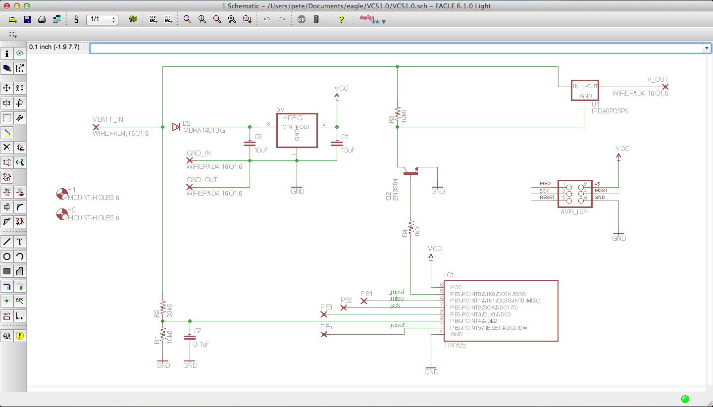
Ok, back to business. Below is a screen cap of the schematic drawn in Eagle. VBATT_IN is the 12 V DC car battery power. It is fed into D2 for reverse polarity protection before heading to a 5 V DC regulator. Prior to D1, the VBATT_IN voltage is also feeding a voltage divider of R1 and R2 and 48 Hz LPF with R2 & C2. The resulting voltage is an attenuated analog of VBATT_IN fed to the ATTiny85 microcontroller ADC.
With the ATTiny85 able to measure system voltage, it can now determine when the car is running ~14 V DC with the alternator running, ~12 with the engine off. We will talk about the program some more later on.
R4 feeds the base of Q2 which pulls down the gate of U1, which is otherwise held high by R3. U1 is an IPD90P03P4 mosfet. It has an RdsON of only 4.5 mOhms which; in testing, allowed me to comfortably pass about 200 watts at ~13.5 V with no heat sink.
Further down is a link to the Mobile Radio Power Controller ( MRPC ) Bill of Materials ( BOM ). The voltage regulator I used is an obsolete part. You should select a new one if you decide to build a MRPC board. Another reason to select a different regulator would be because the one I use draws a shameful 5 mA quiescent current. I might recommend something like an LD1117.
I had these boards fabbed thru the OSH Park service. It was my first time using OSH Park, and at the time of this writing, 50% of of my OSH Park orders have been for MRPC boards.
If you would like to order one of the boards, well you can't, you have to order 3. It's the OSH Park rules. The good news is that those 3 boards will only cost you $9.05, at the time of this writing, for each multiple of 3. For the record, I am not affiliated with OSH Park and no money goes to me if you do purchase a board thru them. Here is a link to the PCB order page https://oshpark.com/shared_projects/jAyTdKon
The circuit board is housed in a custom enclosure I designed in AutoCad. The *.stl was exported, sliced in Slic3r and printed on my Prusa 3D printer. The material I used is Red PLA. I have uploaded the *.stl files so you can print your own at http://www.thingiverse.com/thing:495167
The software is pretty straight forward. Basically, the code tells the processor to sleep forever. This is to reduce power. The watchdog timer will wake the processor up once per second. At this time an ADC conversion is initiated. If the system ( car ) voltage is above a threshold, the event is logged. If the voltage exceeds the threshold for a period of time, the mosfet is switched ON. If neither threshold is met, the mosfet stays OFF appropriately. Everything should be commented, but if you have any questions, feel free to email me.
Downloads:
Here you can download the project archive.
Here you can download the Eagle PCB files
Here is the link to order a PCB
I think that's about it. Let me know if you end up building one for yourself!


Comments